My Homebrew RTB D99 is an advanced, open-source decoder core (AVR64DA48) designed for serious modelers. It provides individual, high-density control for up to 32 LEDs and 4 auxiliary ports. More than just control, this core is engineered for ultimate reliability:
- Flicker-Free Power: Includes charging logic for external Polymer or Supercapacitors for robust power backup.
- Real-Time Diagnostics: Harness the power of Railcom DYN to transmit vital data, including Quality of Service (QoS), track voltage, and temperature, back to your central station.
- DIY High-Density: Fully open-source KiCad design (4-layer PCB) ready for reflow assembly.
- WS28xx bus: Can drive up to 32 LEDs on a WS28xx serial bus
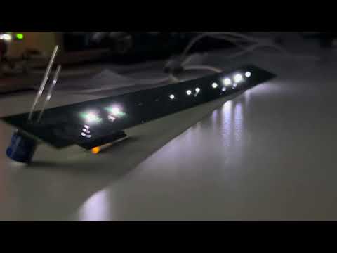
LED base carrier
User Guides
- User Guide - DE
- User Guide - EN

- DCC
- DCC-A automatic logon
- DCC-R protocol extension
- Service Mode Programming
- Railcom
- Channel 1/2
- POM, xPOM
- DYN: QoS, Track-Voltage, Scap-Voltage, Temp, Ambient light
- AUX ports
- 4 AUX ports (3.3V logic level)
- AUX ports my be used for Servo
- LED ports
- designed for
- SR: 74HC595 shift registers
- WS: WS2811 neo pixel
- up to 32 individual LEDs using either SR or WS
- designed for
- SUSI 3.3V
- 2.8V SCAP (optional, external to PCB)
- 16V Polymer Caps (optional, external to PCB)
- Inrush limited
- max track voltage 36V
- CPU heartbeat LED
- ambient light sensor (optional)
- fast firmware update on main tracks via DCC-R
The current PCB layout uses SMD footprints with 0.4mm pitch and mainly 0402 parts. Reflow soldering is mandatory. The layout has been optimized to automatic PCB assembly.
| top | bottom |
|---|---|
 |
 |
- 4-layer PCB, FR4, 28 x 15 x 0.8mm
- CPU: AVR64DA48
Details

| pin | label | direction | description |
|---|---|---|---|
| 1 | DCC-b | input | DCC signal from track |
| 3 | DCC-1 | input | DCC signal from track |
| 5 | GND | output | Decoder ground signal (after rectifier) |
| 7 | AUX-4 | output | Logic level auxiliary port (3.3V) |
| 9 | AUX-3 | output | Logic level auxiliary port (3.3V) |
| 11 | AUX-2 | output | Logic level auxiliary port (3.3V) |
| 13 | AUX-1 | output | Logic level auxiliary port (3.3V) |
| 15 | GND | output | same as pin 5 |
| 17 | VTRK | output | (+) Track voltage after rectifier (goes up to 25V) |
| 19 | NCAP | output | (+) Connect to external polymer capacitors (cap must tolerate 16V) |
| 2 | 3V3 | output | (+) Decoder CPU voltage (3.3V) |
| 4 | SUSI_clk | output | SUSI clock signal (3.3V) |
| 6 | SUSI_dat | output | SUSI data signal (3.3V) |
| 8 | uOpto | input | Connects an optional ambient light sensor |
| 10 | UPDI | in/out | CPU programming port |
| 12 | LED.oe | output | Connect to HC595 shift register output enable pin |
| 14 | LED.stcp | output | Connect to HC595 shift register staging clock pin |
| 16 | LED.ds | output | Connect to HC595 shift register data pin |
| 18 | LED.ds | output | Connect to HC595 shift register shift clock pin |
| 20 | SCAP | output | (+) Connect to external supercap (cap must tolerate 2.8V) |
Filename structure: { pcb }{ code }{ version }.hex
Example: D99F0001.hex
| Description | |
|---|---|
| pcb | Name of matching hardware (D99) |
| code | Type of code contained (R=rom, B=bootloader, F=flash, U=bld update, P=UPDI factory code) |
| version | Release version (####) |
The fuse settings as well as the P-code (D99Pxxxx.hex) has to be installed by using UPDI.
| Fuses Setting |
|---|
 |


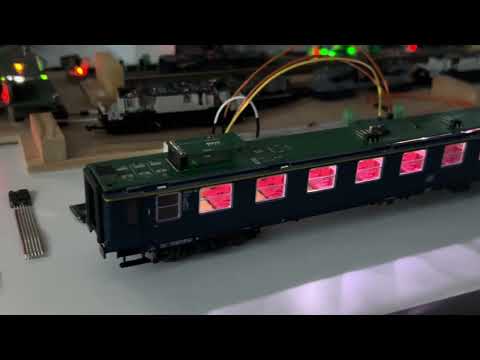
See the D99 decoder core prototype in action piggyback on a LED test carrier.
This project is intended for hobby use only and is distributed in accordance with the Apache License 2.0 agreement.