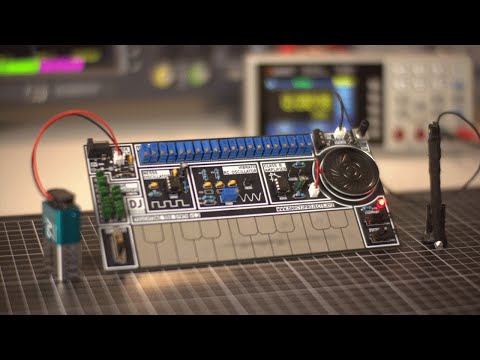
The TouchTone555 is a fully analogue, NE555-based synthesizer designed for learning about analogue electronics, and a bit of fun too. It was built from scratch as a personal deep-dive into oscillators, signal integrity, analogue filtering, and amplification.
Read the full project write up at: www.darcyjprojects.xyz
🔗 Share this project on LinkedIn

This project is open source hardware under the CERN Open Hardware Licence Version 2 - Strongly Reciprocal (CERN-OHL-S v2).
⚖️Disclaimer: This synthesizer was developed as a purely educational project to explore analogue electronics and sound synthesis. It is an independent work inspired by the vintage Stylophone, with no affiliation to Dubreq Ltd. or the original Stylophone product. All trademarks remain the property of their respective owners, and no copyright or trademark infringement is intended.
- Based on the NE555 in astable multivibrator configuration as the main audio oscillator
- Individually tuneable keys with trim potentiometers
- Touch interface for the keys with a stylus
- Octave switching via capacitor bank selection
- Vibrato modulation using an RC oscillator on the 555's CV pin
- Push-pull amplifier output with an LM386 buffer stage
- Onboard speaker with volume control, as well as a headphone output
- Custom designed PCB, with a descriptive silkscreen

Check out the demo video here:
👉 Watch the video
🎵 Features a cover of Littleroot Town from Pokémon.
This project is licenced under the CERN-OHL-S v2 Strongly Reciprocal.
You are free to:
-
Study and modify the design.
-
Make and sell your own copies.
-
Distribute modified versions — as long as you:
-
Use the same CERN-OHL-S v2 licence (strong reciprocity), and
-
Provide attribution to the original author, and
-
Include the original source files and any modifications.
-
For full details, see the LICENCE.txt file.

The TouchTone555 generates sound using an NE555 timer IC which is configured as an astable multivibrator.

Each key forms part of a series resistor network, which controls the oscillator’s frequency when the circuit is completed by touching a key with the stylus. The pitch is determined by which key is touched, and the selected octave capacitor.

Octave switching is achieved by toggling between banks of capacitors connected to the NE555. The more capacitance connected (capacitors in parallel), the lower the resulting octave.

Vibrato is achieved by modulating the NE555's control voltage pin using a separate RC oscillator, which uses RC (resistor-capacitor) pairs, capacitors, and a transistor to generate the low-frequency signal. The vibrato depth (or "mix") can be adjusted with the on-board trim potentiometer.

The output signal is then passed through an LM386 and then through a simple push-pull amplifier to drive the onboard speaker and/or headphones. The LM386 acts as a buffer to ensure any loading from the amplifier doesn't affect the NE555 through its output pin. The supply voltage to the NE555 is also filtered with a resistor and capacitor to reduce any periodic voltage drop introduced by the amplifier.

The power supply circuitry is simple: it supports a 9V DC input via either a JST connector, or a DC barrel jack. Two diodes prevent reverse polarity and ensure that the inputs cannot backfeed each other.

This project demonstrates the core concepts of oscillation, modulation, and amplification - no microcontroller required!
👉 For a full breakdown and more detail explanations, you can read the write-up here: www.darcyjprojects.xyz

- All components as outlined in the BOM (Bill-of-Materials)
- To find the correct switches, speaker, audio jack, etc, see Miscellaneous Parts
- PCB (See KiCad Project)
- Soldering iron and solder
- 9V Battery and connector or DC jack with 9V supply
- Read each step fully before completing it to make sure you've read any handy tips :)
-
Order the PCB
The KiCad project files (and pre-exported gerber files) are located in /hardware. -
Solder components in order
Start with the smallest passive components (resistors, monolithic capacitors, diodes), then IC sockets, transistors, connectors/jacks/switches, ceramic and polyester capacitors, and finally the DC jack, trim potentiometers and the volume potentiometer.Soldering them systematically from smallest height to largest makes it a lot easier! Follow the component designators on the board, and in the BOM to make sure you are matching the correct values and components.
Try your best not to get any solder on the exposed key pads, if you're nervous, you can tape over them with some electrical or painters tape until you're finished soldering.
For the polyester octave capacitors, try to get the values matched to each other as closely as possible as a small variance of 0.5 nF can throw off the pitch. This is less important for the lower octaves, but the highest octave with the single capacitor matters the most.
For the vibrato monolithic capacitors, you can start with soldering the top three in, and adding the lower two if you want increase the vibrato frequency.
-
Attach speaker & power
The synth is designed to run on 9VDC, so I recommend using a 9V battery with a 9V battery to JST connector. -
Stylus
In /hardware, there is a 3D model of a stylus if you'd like to 3D print one, otherwise, a crocodile lead works really well too - just be careful not to push down too aggressively as to not damage the key pads.
If you take the 3D model route, you can feed a thin gauge wire through the hole in the centre of the stylus, and solder a small piece of metal to the wire at the tip of the stylus. I used a mini spade connector which I soldered and then bent around the tip. I smoothed out the contact surface by creating a sphere of solder. You'll need to tape the tip to the stylus to ensure it doesn't come off. This stylus isn't perfect, but it works :)
-
Tune keys
Use a tuner app (with a chromatic mode) or oscilloscope to set the individual key pitches via the blue trim potentiometers.Set the octave to the lowest octave (lowest position on the octave switch) and then start tuning with the highest note on the keyboard, which corresponds to the right-most trim pot. Turning it clockwise will increase the pitch, and anticlockwise will decrease the pitch. You are aiming for the highest note (in the lowest octave) to be E6.
Then work your way leftwards, one potentiometer at a time, reducing the pitch by one semitone each time.
Remember, as this is a series resistor network, adjusting the pitch of one potentiometer will adjust the pitch of all the other keys to the left of that key. This is why you should work right to left.
-
Vibrato depth
By turning the vibrato depth trim pot, you can slightly adjust how strong the vibrato effect is. The change with each turn is minimal, so you'll need to turn it a lot to get any real difference. -
Have fun!
TouchTone555/
├── hardware/ # KiCad project + Gerbers + Stylus 3D model
├── media/ # Photos, demo videos, renders, etc
├── LICENCE # CERN-OHL-S v2
└── README.md # this file!
Feel free to fork, share, and build your own!
If you build one, I’d love to see it - tag me on LinkedIn.
- This is an independent work inspired by the classic Stylophone with no affiliation to Dubreq Ltd. or the original Stylophone product. All trademarks remain the property of their respective owners, and no copyright or trademark infringement is intended.
- "Littleroot Town", composed by Gō Ichinose, Junichi Masuda, & Morikazu Aoki, from Pokémon Ruby, Sapphire, & Emerald (© Nintendo / Game Freak), is used under fair use as part of an educational demonstration.
This was a personal challenge to push my understanding of analogue electronics beyond textbooks — especially in:
- Oscillator design
- Filtering
- Operational amplifiers
- Audio amplifiers
- Impedance buffering
- PCB design with custom exposed planes (the key pads)
- PCB footprint design

🛠️ Built for learning.
❤️ Shared with the community.
🔧 Darcy — www.darcyjprojects.xyz